Digital logic design: binary parallel adder/subtractor Demo: 4-bit adder subtractor using full adder ic with tinkercad Solved adder and subtractor 4 bit circuit i have the next
Solved Design a 4-bit adder/subtractor using the 7483 and | Chegg.com
Adder serial subtractor module schematics
Adder subtractor bit circuit add sub overflow complement logic detection carry addition designing control zero line questions find digital
Please, design a 4-bit binary adder-subtractor. yo...Adder subtractor bit binary please electrical engineering modular con chegg answers questions Adder subtractor bit parallel bcd circuit adders using circuits arithmetic ppt powerpoint presentationSolved: consider the 4-bit adder/subtractor circuit displa....
Adder bit subtractor circuit values consider following input mode has help steps solve thank displayed figure questions solvedBit adder subtractor circuit carry ripple logic Subtractor adder bit circuit logisim using pint schematic7483 adder bit subtractor using circuit binary input gates subtract logic solved complement diagram block answer problem been add has.

Logic adder subtractor parallel binary circuit bit diagram control signal mode digital determines which has
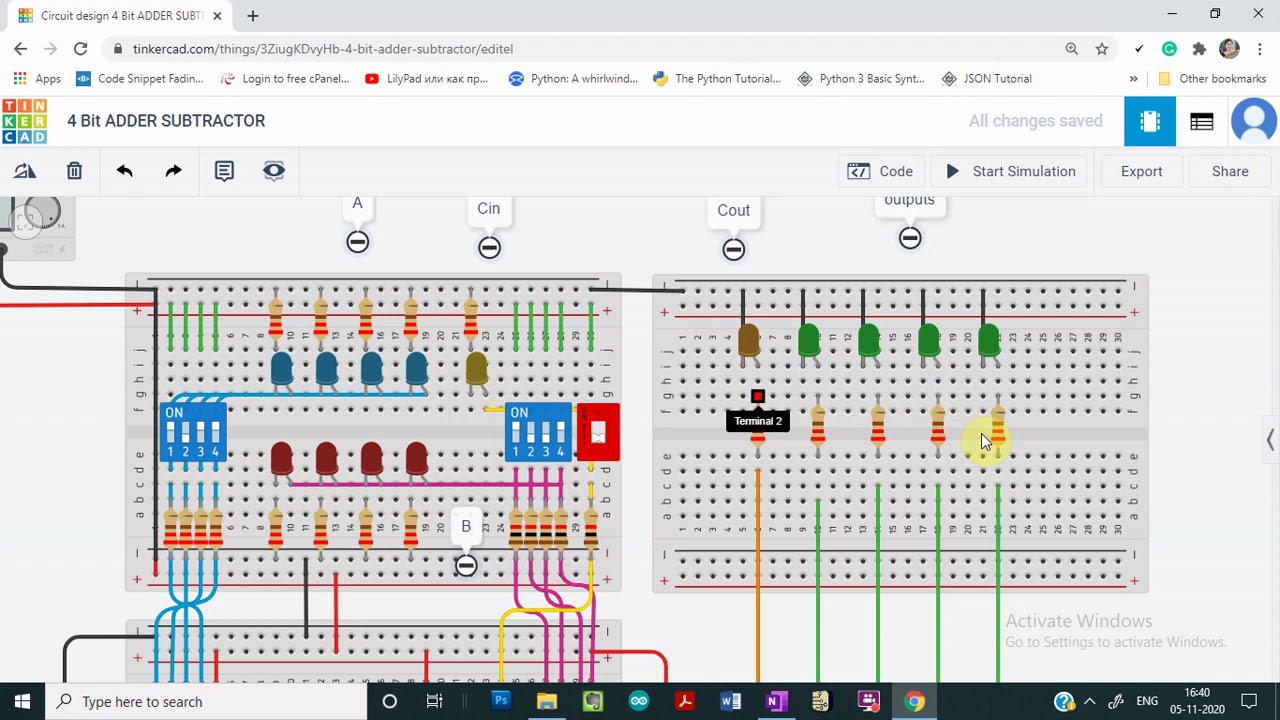
Digital logicAdder subtractor tinkercad 4-bit serial adder/subtractor with parallel load – altynbek isabekovDraw the logic diagram of a full adder. create a 2-bit adder-subtractor.
Let's learn computing: 4 bit adder/subtractor circuit .